As we all know about the turbine. They have vast application and can be classified in different ways. According to water flowing through the turbine runners, turbines are classified in two categories i.e. impulse turbines and reaction turbines. Pelton wheel turbine is the type of impulse turbine but here we talk about only reaction turbine.
A reaction turbine is different from impulse turbine in many ways. In reaction turbine pressure is not remains same throughout the turbine. When water enters into the turbine runner, one part of the available energy of water converts into kinetic energy and remaining part converts into pressure energy.
The pressure varies throughout the turbine. At the entrance of turbine pressure is much higher than the pressure at exit. When water starts flows through the runner the pressure energy starts converts into kinetic energy. Due to variation in pressure the casing of the turbine should be air tight and always full with water. At the entrance pressure is equal to atmospheric pressure but in runner’s pressure starts decreases and it is less than atmospheric pressure. This difference in pressure is the reason of flowing of liquids i.e. liquid flow high pressure region to lower pressure region. The difference between the pressures of runner is known as reaction pressure and these types of turbines are known as reaction turbine. Francis, Propeller and Kaplan are the some commonly used reaction turbines.
Operating Conditions:
Generally reaction turbines are medium and low head turbines with medium and high discharge.
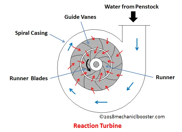
Reaction Turbine:
Construction:
Reaction turbine has various components which are given as follow
Reservoir:
Reservoir is a large area where water stores. It is continuous source of water with large amount of hydraulic energy. This can be natural as lake or may be artificial called as dam. Large quantity of water store here for continuous supply of water.
Penstock:
Penstock is a large diameter pipe which is used to carry the water from reservoir to turbine.
Surge tank:
Surge tank is a type of reservoir of water located near to the turbine which is used to avoid water hammering in penstock.
Casing:
Casing is made up of cast steel, plate steel or may be concrete depending upon the working conditions of turbine. It is spiral in shape and gradually decreasing in area. The purpose of the casing is to provide constant velocity of water at the inlet of the runner and to maintain the constant velocity for the water. Gradually decreasing area helps to maintain the constant velocity of water throughout the runner.
Guide vanes and fixed vanes:
Fixed vanes have two functions. It guides the water from casing to guide vanes and it also helps in distribution of load due to internal pressure of water. These fixed vanes are generally made up of cast iron, cast steel or fabricated steel.
The guide vanes use to guide the water towards the runner in guide vane angle direction. These vanes are fixed but can rotate about their own axis. The guide vanes are airfoil in shape and generally made up of cast steel, stainless steel and plate steel. These guides vanes are controlled with the help of governor by controlling flow area to control the discharge or may be operated either by means of wheel in case of small units.
Runner:
The runner of reaction turbines generally consists of series of curved vanes mounted circumstantially in the angular space between two plates. These curved vanes are 16 to 24 in number. The runner is generally made up of cast iron, cast steel, or stainless steel. To reduce the cost only some portion of the runner usually made up of stainless steel which subjected to cavitation. The runner is joins with the shaft for power transmission. The torque generated by the runner by the help of hydraulic energy of water is transferred to generator though shaft. This shaft is joins with bolted flange connection.
The runner may be different types as per the requirements. Different turbines have different type of runner because the flow of water is different in all the turbines. Reaction turbines are classifies according to the direction of flow of water with respect to runner. These are axial flow, radial flow and mixed flow type runners. In Kaplan and propeller shaft turbines axial flow runner is used where as in Francis turbine radial flow runner in use. In special case we use mixed flow runner i.e. in modern Francis turbine. So selection of type of runners is depends only on the type of turbines.
Draft tube:
Draft tube is the major component in case of reaction turbines, we have no requirement of draft tube in case of impulse turbine. Draft tube is a pipe with gradually increase in cross sectional area. It is fitted at the runner exit to tail race. Draft tube is used to convert the kinetic energy into pressure energy in order to increase the efficiency of the turbine. It is made up of cast steel, plate steel or may be of concrete. Draft tube must be air tight in all conditions and the lower part of the draft tube must be submerged into the water of tail race up to some level. The draft tube used can be of different shape and sizes as per the requirements.
Working:
Water is supplied by penstock from reservoir to turbine than enters into the casing. Casing is completely surrounds the runner. This casing distributes the water circumferentially into the runner of turbine. This casing always filled with water. Inside the casing number of fixed vanes present, this converts the head available with water partially into dynamic head. The cross sectional area of the casing gradually decreases to maintain the constant velocity of water throughout into the turbine runner. These various components and vanes help in flowing of water into the runner with minimum loss of energy.
When the water enters over the rotor in the runner it has both kinetic energy and pressure energy. When the water strikes over the moving vanes/ curved vanes it applies impulse force due to kinetic energy same as in case of Pelton wheel. As the water flows over the moving/curved vane it creates a pressure difference across the vane due to air foil shape of the vane, due to which water applies the lift force over the vane. This lift force is also known as reaction force. The impulse and reaction force will rotates the runner. Due to this reason sometimes it is also called as impulse reaction turbine. After runner water is out through the draft tube which is attached at the bottom of the runner. The draft tube provides suction head at the runner exit. The exit water goes into the tail race which further utilize in various applications.
This is all about basic of reaction turbine. All reaction turbine works on this principle. If you have any query regarding this article, ask by commenting. If you like this article, don’t forget to share it on social networks. Thanks for reading it.


