When a body is moving with a velocity in a fluid making some angle with the stream line of the fluid flow experiences some force acting on the body. The component of force acting along the stream line is called Drag and the component of force acting orthogonal (perpendicular) to the stream line is called lift. The weight of the body acts downwards and the thrust force produced by the body is along with the body in the same direction.
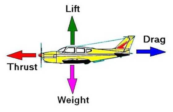
Lift and drag are the aerodynamic forces that an object in a fluid will experience due to its motion.
The fluid may be gas or liquid.
If the fluid is gas then the forces are called aerodynamic forces, if the fluid is liquid then the forces are called hydrodynamic forces.
LIFT :
Lift is the perpendicular force executed by the fluid ( Eg : air ) on the body.
Lift is generated by the combination of Bernoulli’s principle and Newton’s third law.
- Pressure difference between the upper surface area and lower surface area of an aerofoil.
- Upward forward force acting on the wing due to the reaction of downward backward flow.
(Downward and backward flow of air from the top surface of wing creates a downwash, this downwash meets the flow from the bottom of the wing at the trailing edge, applying Newton’s third law to reaction of this downward backward flow results in a upward forward force on a wing. )
Lift is perpendicular to relative airflow or flight path or drag.
There are two types of lift:
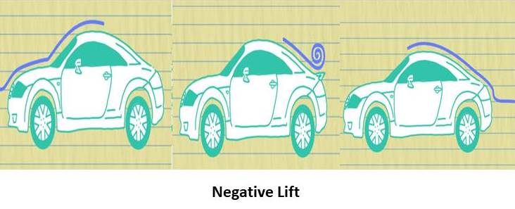
- Positive lift ( acts upward )
- Negative lift ( acts downward )
If we consider an aeroplane which have positive lift.
The governing equation for lift
L = ( 1 /2 ) ρ V2 S CL
Where
CL = coefficient of lift ( no units )
ρ = Density of air ( kg / m3 )
V2 = Velocity of airplane ( TRUE AIR SPEED of plane ) ( m/s ) => ( m/s )2 => (m2/s2)
S = surface area of wing ( m2 )
In the above equation the term [( 1 /2 ) ρ V2 ] is called Indicated Air Speed ( IAS ) or Dynamic Pressure.
TAS = RAS + 2% of RAS/1000feet
(RAS/1000feet => RAS per 1000 feet)
TAS = True Air Speed
RAS = Rectified air speed or Calibrated air speed
Coefficient of lift depends on camber and Angle of attack.
| Camber ( depending on the air craft design ) | Speed ( obtained ) | Lift ( obtained ) |
| High camber | Low speed | High lift |
| Low camber | High sped | Low lift |
Some of the conditions to maintain constant lift
- when the altitude increases density decreases, so to maintain constant lift velocity should be increased.
- At fixed altitude if speed is increased or decreased, to maintain a constant lift angle of attack has to be decreased or increased ( adjusted ).
- When altitude is increased density decreases, if true air speed is kept constant the amount of air flowing over the wing decreases and hence lift decreases.
- If the indicated air speed is kept constant and angle of attack also kept constant, planes even though they are flying at different altitude will produce same lift.
Graph for Coefficient of Lift and Angle of Attack:
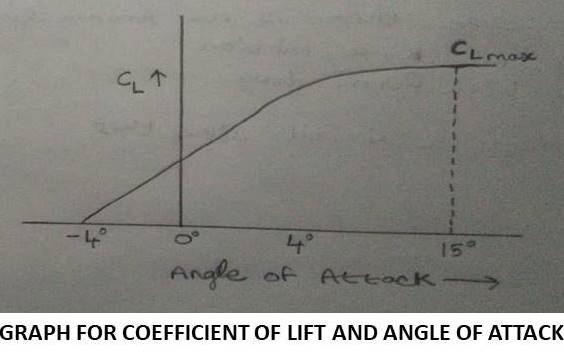
At angle of attack of -40 lift is zero.
At angle of attack of 00 lift is somewhat and CL is positive.
From 00 to 120 increase of CL is steady.
From 120 to 150 increase of CL is at lower rate.
If angle of attack greater than 150 , CL decreases rapidly.
CL MAX occurs at an angle of attack of 150 and its standard value is 1.52.
CL is measure of lifting effectiveness.
NOTE :
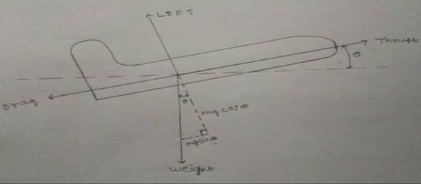
When the airplane is in equilibrium we can calculate lift by using the formulae L = mg cosθ
m = mass of the airplane
g = acceleration due to gravity
Weight of the airplane ( W ) = mg
The equation L = mg cosθ shows the only minimum value.
So L ≥ mg cosθ when the airplane is to takeoff.
Positive lift is used for aeroplanes, helicopters, etc.
Negative lift is used in the automobiles ( Eg : spoiler in race cars ) to have more grip.
The direction in which the wing is mounted determines whether positive lift or negative lift is generated.
DRAG :
Drag force is the resisting force caused by motion of a body through a fluid.
From Newton’s Third law Drag is the opposite reaction caused due to motion through fluid.
Drag is parallel to relative airflow, opposite in direction to flight path.
Based upon the lift, drag is classified
- Parasite Drag ( Non – lifting type drag )
- Profile Drag
- Form Drag
- Skin Friction Drag
- Interference Drag
- Induced Drag ( produced due to lift )
FORM DRAG :
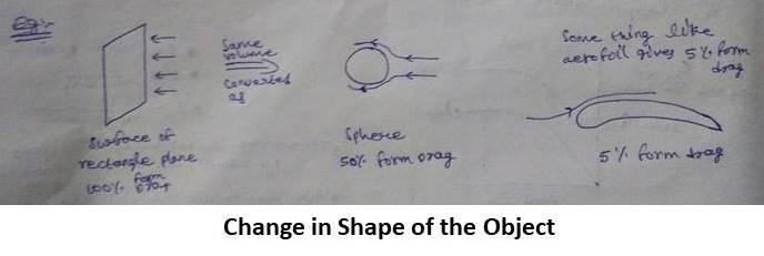
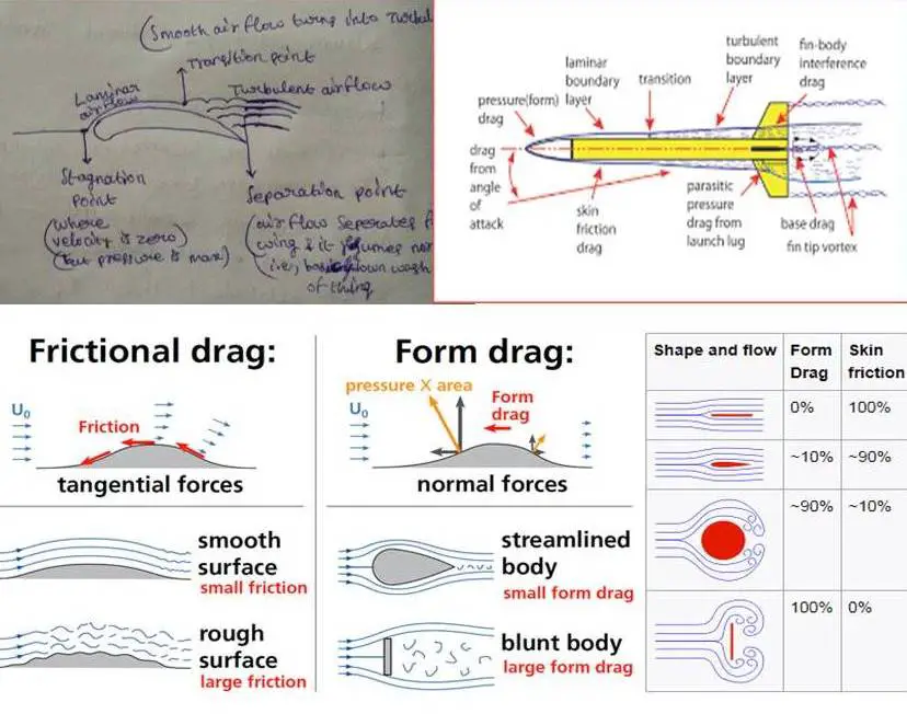
Form drag is caused due to pressure difference ( between front and rear of the object ), especially due to low pressure.
Form drag occurs based on the shape or profile of the body.
Form drag can be reduced by aerodynamically stream lining the shape of the body, but it cannot be made zero.
Eg: If we take a rectangular plane surface it has 100% form drag. If the same volume is converted to sphere it has 50% form drag. And by changing its shape to aerofoil only 5% form drag occurs. But we cannot neglect form drag.
SKIN FRICTION DRAG :
The momentum of free stream loss through the boundary layer is said to be skin friction drag. Skin Friction Drag is due to retarded boundary layer in contact with aircraft skin. It depends upon the smoothness of the aircraft surface. Surface with more smoothness results less skin friction drag.
INTERFERENCE DRAG :
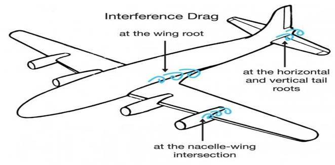
Interference drag occurs because of joints. It can be prevented by smoothening the joints.
Eg : some places where interference drag occurs are
- Wing fuselage joint (root of the wing joining the fuselage).
- Wing engine joint ( called nacelle )
Factors affecting parasite drag are :
1.Indicated air speed ( IAS )
Parasite drag is directly proportional to square of IAS.
Parasite drag α ( IAS )2
2. Shape
Shape of the body with aerofoil streamline will have less parasite drag.
3. Surface smoothness
Surface with more smoothness reduces the parasite drag.
4. Surface area
Increase in surface area increases parasite drag.
5. Configuration of aircraft
Parasite drag increases by 80% due to flaps, landing gear, etc.
Factors that do not affect parasite drag :
1. Altitude
During flying aircraft is flew constantly, So IAS remains constant so that parasite drag is not affected.
2. Angle of attack
Angle of attack does not affect parasite drag.
INDUCED DRAG :
Induced drag occurs due to wing tip vortices and trailing edge vortices.
Wing tip vortices are due to high pressure air below the wing swirling over upwards and outwards at the wing tip towards the low pressure area on the upper surface, and airflow movement is clockwise on the left wing and anticlockwise on the right wing.
Trailing edge vortices occurs when the airflow over the wing is inwards and towards the fuselage due to low pressure on the top surfaces and outward on the below surfaces, resulting in conflict meeting at the trailing edge causing induced drag ( this is wake turbulence ).

Factors affecting induced drag :
1.Indicated air speed
Induced drag is inversely proportional to the square of Indicated air speed.
Induced drag α ( 1/ Indicated air speed )2
i.e., if we have more speed it results less induced drag.
2. Aspect ratio
Induced drag is inversely proportional to Aspect ratio.
Induced drag α ( 1/ Aspect ratio )
i.e., if we have high aspect ratio it results less induced drag.
( reason : higher aspect ratio means the wing span is higher and less induced drag occurs. )
Wings having high aspect ratio are more efficient.
3. Lift
Induced drag is proportional to square of lift.
Induced drag α ( lift )2
Induced drag increases with increase in lift.
4. Load factor
Induced drag is proportional to load factor
Induced drag α load factor
Formulae related to induced drag coefficient Cdi = ( CL )2 /AR
General equation for Drag D = ( 1 /2 ) ρ V2 S Cd
Where Cd = coefficient of drag ( no units ) = coefficient of parasite drag + coefficient of induced drag
METHODS TO REDUCE INDUCED DRAG :
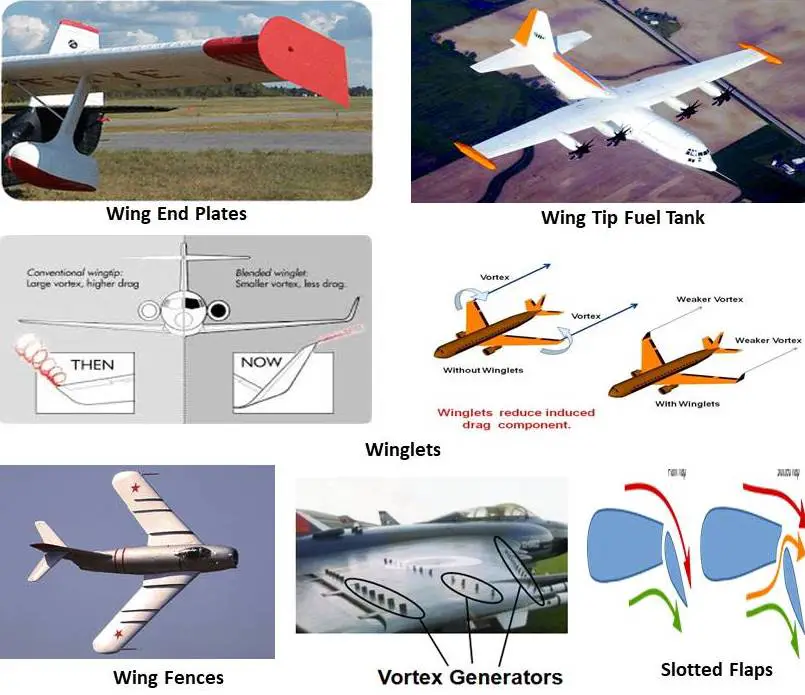
1.Wing end plates
Plates are placed at the end of the wing to reduce induced drag. Plates are placed up or down based on the design of manufacturer.
2. Wing tip fuel tanks
Fuel tanks are placed at the end of the wing, which reduces induced drag as the wing tip vortices won’t be able to meet the air flow from the above.
3. Winglets
Winglets reduce the intensity of wake vortices.
4. Wing tip shape modifications
Depending upon the design shape of the wing tip is modified.
5. Boundary layer
By using the below three equipments, the position of transition point can be changed beyond certain value. So as induced drag reduces.
- 1.Wing fences
Wing fences are triangular shaped structures on the upper surface of the wing.
When air is flowing over the wing there will be slight movement towards the root on the upper surface. Wing fences do not allow air towards the root and hence air flow continues in straight forward direction. This avoids trailing edge vortices, so that wake turbulence and induced drag reduces.
- 2. Vortex generator
When air passes through the vortex generator part of aerofoil transition point moves backwards. This movement of transition point will reduce induced drag.
- 3. Slotted flaps
Slotted flaps re-energises the boundary layer, hence separation happens at delayed point.
GRAPH FOR COEFFICIENT OF DRAG AND ANGLE OF ATTACK :
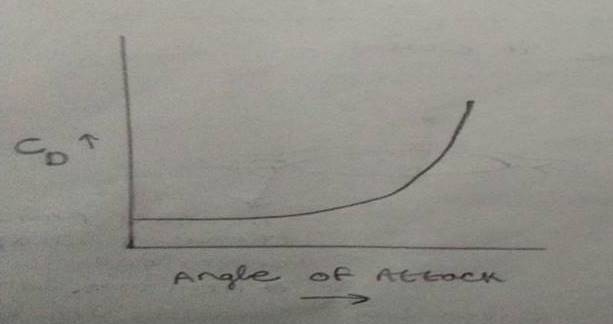
At lower angle of attack CD is increasing but at slower rate and steady rate.
At higher angle of attack CD increases rapidly and further beyond 150 or 160 angle drag increases further exponentially.
GRAPH FOR PARASITE DRAG AND INDUCED DRAG :
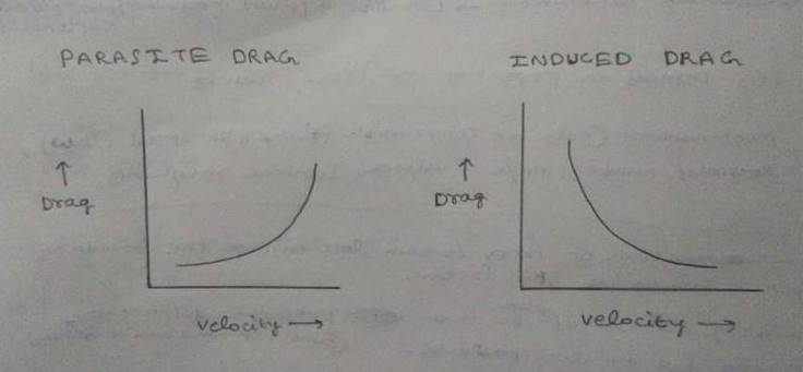
COMBINED GRAPH OF PARASITE DRAG AND INDUCED DRAG :

Drag is least at the point where the both the drag lines intercept, and the point is called VMD or VBR
VMD means minimum drag speed.
VBR means best speed range of velocity.
Total drag line is the resultant of both parasite drag and induced drag.
If anything flown beyond the VMD velocity line, drag will increase.
The speed VMD is important reference for many items of aeroplane like performance, range , endurance, climb, glide, endeavour landing, takeoff performance, etc.
NOTE :
When the airplane is in equilibrium D = T – mg sinθ
Here T = Thrust force
When the airplane is taking off thrust should be greater than drag.
So at the time of taking off drag is D ≤ T – mg sinθ.
STALL :
It is the angle where rapid decrease in CL occurs.
The point where Angle of attack > 150 is called stalling angle or critical angle or bubble point.
That means air is in bubbles blast, smooth flow is lost.
LIFT/DRAG ( L/D ) RATIO :
L/D ratio gives aerodynamic efficiency.
( L/D ) ratio = ( CL/CD ) ratio
L/D ratio is also called glide ratio.
Eg : ( L/D ) = ( 12/1 ) => you will glide 12nm with a loss of 1nm.
nm means nautical mile.
GRAPH OF ( CL/CD ) RATIO AND ANGLE OF ATTACK :

At ( L/D )MAX plane will have maximum efficiency.
Any angle of attack before 40 and after 40, Drag will always increase.
The 40 point is crucial, which is general value for L/D ratio ( i.e. maximum L/D ratio at 40 angle of attack ). At this point drag is least.
The 40 angle of attack point is called as VMD means minimum drag speed or VBR means best speed range of velocity or optimum angle of attack (this is where we get maximum range and maximum efficiency).
In the polar profile graph if we draw a tangent to the CL – CD graph line the intersection point for both the lines is called ( L/D ) MAX .
NOTE :
CL and CD depends upon the properties of flow such as mach number ( only for compressible flow and high speed flow ), Reynolds number, angle of attack, surface roughness.
Lift and Drag also occurs in the moving objects which are submerged and floating, in and on the liquid fluid. ( EG : submarines, speed racing boats )
Wind turbine blades, rockets, missiles, etc have lift and drag.
Chord line is an imaginary line joining the leading edge and trailing edge in a straight path.
Camber line is a line joining the leading edge to trailing edge, but equidistant from the upper and lower surfaces of the aerofoil.
When both the chord line and camber line are co-inside the aerofoil is called symmetric aerofoil.
When chord line and camber line are not co-inside the aerofoil is called Non-symmetric aerofoil.
When the camber line is above chord line it is called positive camber.
When the camber line is below chord line it is called negative camber.

Flow turning at the trailing edge is very important. Higher the turning greater lift is achieved. This effect is used for stability and control of airplane.
Angle between the chord line and relative airflow of an aerofoil is called angle of attack.

IN THIS ARTICLE AIRCRAFT IS TAKEN AS AN EXAMPLE OBJECT.
The shape aerofoil gives the best results, so till now it is not replaced with any other shape.
Aero means air, meaning of foil is to prevent. i.e., preventing the air and moving further.
Aero is preferred spelling in British English, whereas Air is preferred spelling in American English.
Aircraft is any machine that can fly. ( Eg: Airplanes, helicopters, flying platforms )
Airplane is a specific type of aircraft whose design has fixed wings and heavier than air.
Airplane and helicopter both generate lift but flying is different.

